


TODO: transform design doc to application description
Overview
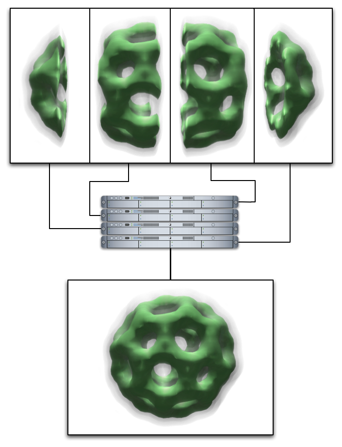
This document gathers some design issues around Equalizer's volume rendering application. A 3D texture based approach was chosen for the implementation. The focus is to render large volumes the volume decomposition using DB (sort-last) compounds. The volume is split into bricks along one axis for simplicity. The recomposition of the partial, semi-transparent volume bricks is done using back-to front compositing. The number of frames to composite equals the data bricks number, the data bricks are in strong correspondence to each other. We only need to transfer RGBA information, and we can ignore depth values on the final compositing stage, which save a network bandwidth. The correct sequences of the RGBA frames for compositing is fixed, but Equalizer's current compositing implementation assumes that frames can be composed in arbitrary way. For the volume render, we will implement a user defined sequence of frame compositing. This technique could be used in future for arbitrary semitransparent objects compositing.
Design
3D Texture-Based approach in volume rendering
The main idea of the 3D texture-based approach is that the volume is stored as a 3D texture on the GPU, and then intersected with viewport-aligned slices rendered in back-to-front order. This algorithm allows to achieve good performance, because GPU will do all the work on texture interpolation. The quality can be improved by using a pre-integrated transfer function [1] p.61,92.
The following pictures illustrate a few slices which intersect the volume. After rendering the slices with blending from back to front, the result image will contain a complete view of the model.
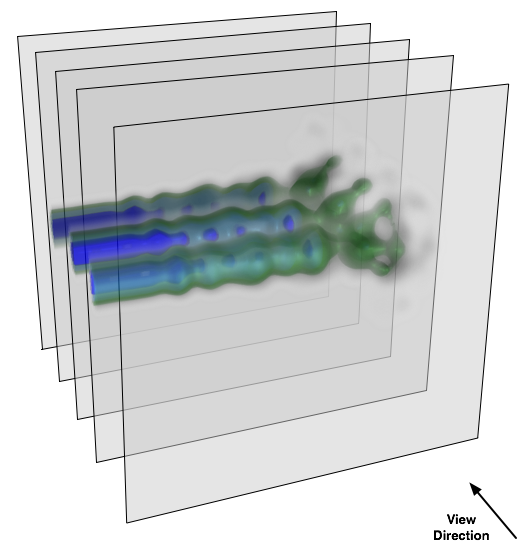
In our eVolve example we are dealing with cubic models (parallelepiped models are treated in the same way, assuming that they are cubic and then scaled to the real shape, which allows using of uniform algorithms for model manipulation). The intersecting viewport-aligned slices are polygons with 3..6 vertices. There is no need to render the rest of a slice, only the intersection is important in order to save computational power. We use algorithm to determine that intersection from [1] p. 73.
DB decomposition in eVolve example and Texture Memory Allocation
In the eVolve example the volume is divided along Z axis for simplicity reasons. It is possible to extend that to decomposition in arbitrary parallelepipeds.
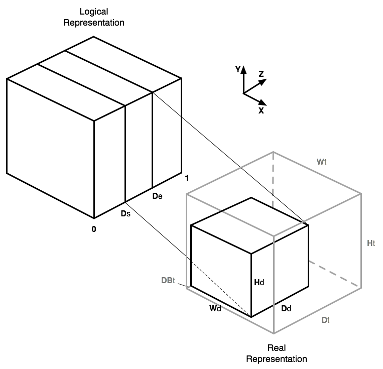
Logically, the volume is represented as a cube with all edges' lengths equal to 1, which corresponds to the texture coordinates in the GPU. The DB decomposition range is a pair of values which belongs to interval [0..1], so we can divide the volume using directly the DB range. The actual 3D texture dimensions should be equal to power of two because of hardware limitations, but in the real world models can have different dimensions. A scaling of the final 3D texture coordinates is required in that case. The scaling of coordinates also should be used to utilize 3D texture memory in an efficient way, there is no need to have free space in the 3D texture which correspond to object slices which are rendered by other clients.
The picture in the right illustrates memory allocation and scaling of 3D texture coordinates processes. Each channel renders parallelepiped of a model which has texture coordinates: [0,0,Ds]..[1,1,De]. This piece of model has dimensions of [ Wd x Hd x Dd ] voxels, the 3D texture has dimensions of [ Wt x Ht x Dt ] pixels. The piece of a model is not stored tightly to the 3D texture edge along the Z axis, but with small threshold for the pre-integration technique, which requires some space in the edge for correct compositing. This shift equals to DBt pixels. The texture coordinates Wd-1, Hd-1, Dd-1 are correspond to 1 in 3D texture coordinates' space, hence the coordinates transformation will look like:
        Xn = X * W
        Yn = Y * H
        Zn = Db + ( Z - Ds ) * D
where:
        W = Wd / Wh
        H = Hd / Hh
        Db = DBT / Dh
        D = ( Dd / Dh ) / ( De - Ds )

        X, Y, Z - original texture coordinates
        Xn, Yn, Zn - new 3D texture coordinates
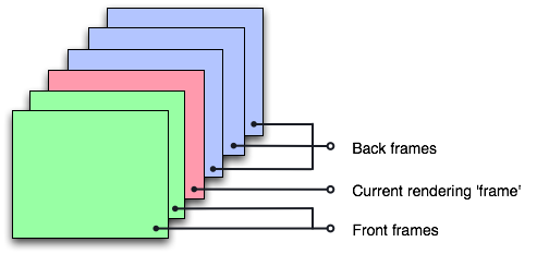
Semi-transparent frame compositing
Since the current compositing implementation assumes no order, the currently rendered plane in the frame buffer already and we don't need to read it back for compositing. For volume rendering, this plane is often not the last one in the compositing order. There are two ways to solve the problem:
-
The channel that performs the compositing should wait for all frames that
should be assembled before him, perform the compositing of this planes, then
render his own data over already assembled planes, and finally assemble all
frame which should be drawn in front of his. This process could be
schematically described as following:
      clear
      assemble "pre"
      render
      assemble "post"
It introduces 1 frame latency which is not a problem. However this approach has the following problems: only one client can perform compositing (serial assembly) and parallel compositing algorithms, such as direct send, couldn't be used. This approach could be possibly used only when semitransparent objects covers small area of a frame. -
The second approach uses a read-back of assembling area so theoretically it
should be slower but it doesn't introduce latency and could be done in
parallel so it will work much faster, plus it will take less effort to
implement. Its order of operations is:
      clear
      render
      read-back
      assemble
Please note that read-back should be used only for compositing area and only when the current brick is not the farthest one.
A more detailed sequence for the second algorithm is:
    override Channel::frameAssembly()

    - compute union of frames -> uPVP (unionn pixel viewport);

    * read image of uPVP

    * glClear( uPVP )

    - push GL state, set up blending

    - draw all frames ordered (range and current transformation matrix
      should be used to obtain correct assembling sequence)

    - restore GL state

    * free/recycle image
Stages marked with (*) should be performed only when the current
brick is not the farthest one. The assembly stage should be omitted
in case of 2D (Sort First) composition.
Correct Frames Compositing Order Computation
In order to perform back to front compositing, we need the right order of DB slices. There are two different cases implemented in eVolve: for perspective and parallel projection.
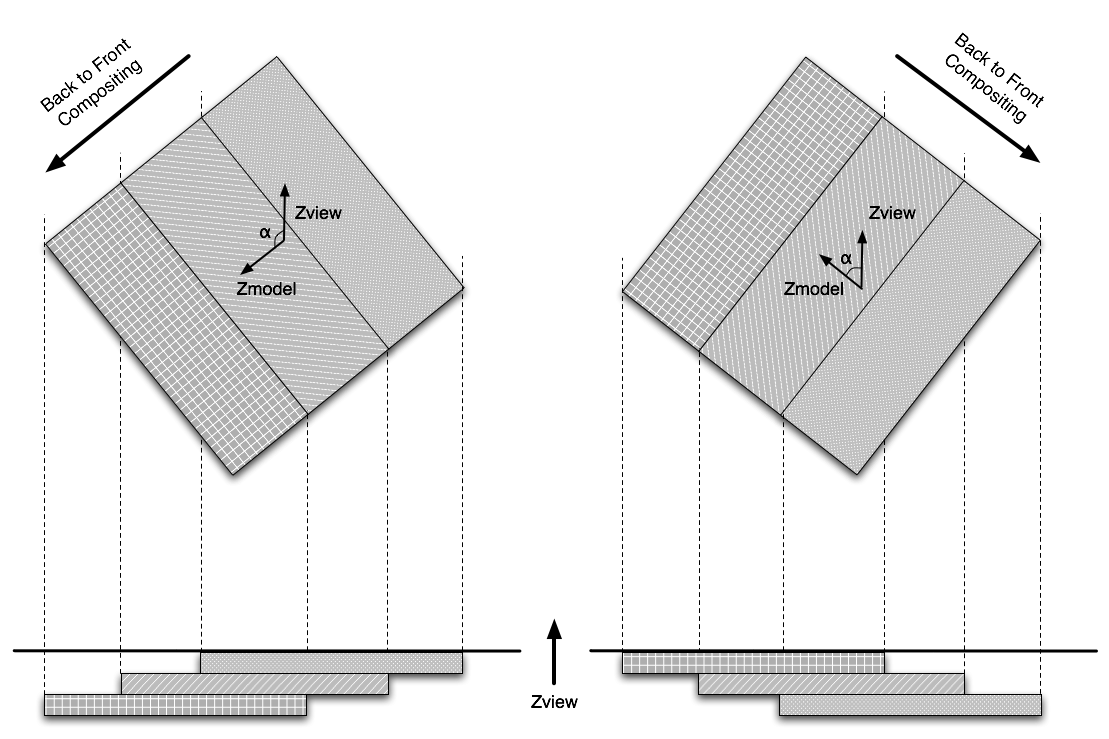
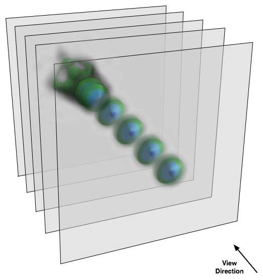
As it is described above, volume model is divided along Z axis. The compositing order is defined according to the angle between view vector and vector which is parallel to the Z axis in model-space (vector [0,0,1]). The compositing order should be switched if that angle is more than 90 degrees, as shown in the first picture below. In fact we only need to check a sign of one element of the rotation matrix which corresponds to cos(Ax)*cos(Ay), where Ax and Ay are angles or rotation around X and Y axes.
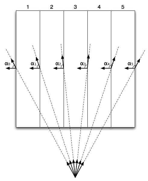
The perspective projection case is more complicated as you can see from the picture on the right. In that picture the right compositing order would be: slices 1,2,5,4,3 or 5,4,1,2,3 (and other variants with slices 2 and 4 after slices 1 and 5, with slice 3 on top) because of the perspective distortion. To calculate the right order we have to check several angles now, two angles per slice. Our algorithm finds the first slice where the change of sign of cos of angle happens, and changes order of the rest slices.
Implementation
TBD
API
TBD
File Format
TBD
Open Issues
References
[1] Klaus Engel, Markus Hadwiger, Joe M.Kniss, Christof Rezk-Salama, Daniel Weiskopf. "Real-Time Volume Graphics." A K Peters, Ltd, 2006.