

Author: eilemann@gmail.com
State:
- Implemented in 0.2
- HMD: implemented in 0.9
- Observers: implemented in 0.9
- Focal Distance: implemented in 1.2
Overview
For stereo viewing, typically two different views are rendered, one for each eye. The display setup ensures that each eye sees the correct view, either by time-multiplexing the left/right images (active stereo) or by using polarization filters (passive stereo). Some autostereoscopic or holographic displays require more than two views, since the project to multiple viewer positions in space.
Head tracking is often used with stereo rendering. The viewer position is tracked, and the rendering is adapted to give the observer the illusion of a fixed scene in 3D space.
Stereo Rendering
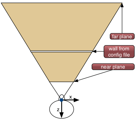
Equalizer uses the notion of an eye pass in the compound specification. If
nothing is specified, the compound renders one view for monoscopic viewing,
for the CYCLOP eye, as shown on the right. With the
compound's eye field the eye passes are specified. The eye passes
are inherited to children, unless the children overwrite the eye field.
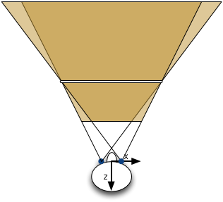
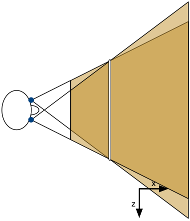
To use active stereo, the window has to have a stereo visual and the
compound has to specify the left and right eye using
eye [ LEFT RIGHT ]. Equalizer then executes two rendering passes,
and uses the eye base to adjust the view frusta as shown on the left.
For passive stereo, two output channels are used and projected onto the same surface. Typically two compounds would be used, one rendering the left eye using the channel connected to the left projector, and the other rendering the right eye using the same wall description.
The window attribute hint_stereo can be used to request a
quad-buffered stereo visual. The distance between the left and right eye is
specified using the config attribute eye_base.
Immersive Visualization
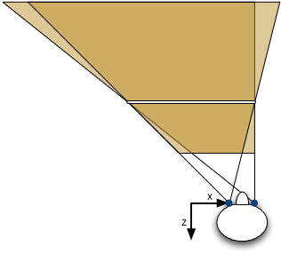
For immersive installations, the head position is tracked and view frusta are
adapted to the viewers position and orientation, as shown on the right. The
head position is reported by the application
using Config::setHeadMatrix, which is used by the server to
compute the eye positions (cyclop, left, right). These eye positions, together
with the wall description, are used to compute an OpenGL frustum and the head
transformation to position the frustum. The default head matrix is an identity
matrix, thus the default eye positions are ( +-eye_base/2, 0, 0
), as shown above in the stereoscopic view frusta.
Head-Mounted Displays (HMD)
Head-mounted displays move the display 'wall' with the observer, they are fixed in front of the viewer. In Equalizer terms, the head matrix defines the position of the wall. The eyes and the frustum are using the head matrix.
HMD's are configured using a wall description. When the type of the wall description is set to HMD, the frustum is tracked using the current head matrix.
Multiple Observers
The configuration holds a list of observers. Each observer has its own head matrix and eye separation. One observer tracks multiple views. For further information on multiple observer and their integration with the Layout API please refer to the specification.
Focal Distance
Fixed Focal Distance
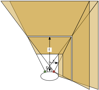
The focal distance defines at which range the left and right eye converge into the same image. Objects placed at the focal distance do not have a stereo divergence.
In the current implementation (0.9.3), the focal distance is equal to the physical projection wall, as shown in the right image. As the observer moves closer to a wall, the focal distance converges to 0 and often causes discomfort, when the observer is looking at a model behind the physical wall since the rendered focal distance does not correspond to the viewed focal distance.
The application has to be able to set the focal distance
using Observer::setFocalDistance. The focal distance is either
given by the user, depending on the scene, or calculated automatically, e.g.,
by using the distance of the closest object in the view direction.
Focal Distance relative to World
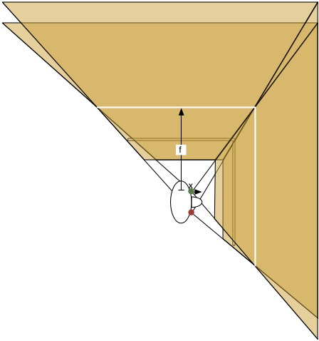
The first implementation computes the focal distance relative to the origin, as shown on the right. This setting might change on a per-frame basis. When the observer moves, the focal distance between the observer and the focused object changes. While this is not semantically correct, it has the benefit of providing a stable convergence plane (see second implementation below).
Implementation:
See below, except use identity head matrix for ratio computation.
Focal Distance relative to Observer
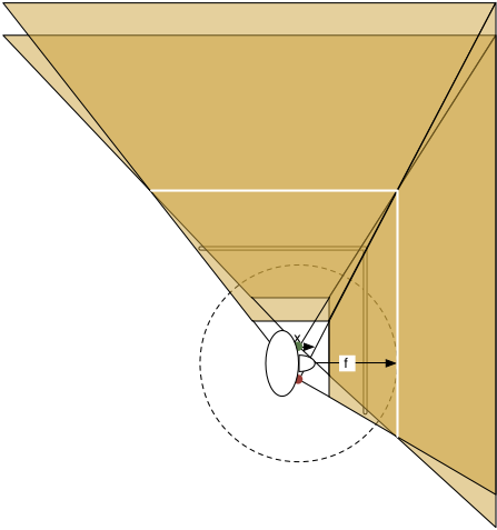
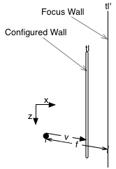
The second implementation computes the focal distance relative to the observer, as shown on the right. The observer view direction determines the focal plane, as described in the following paragraph. This causes the stereo convergence to change continously as the observer looks around, which might not be comfortable. This is shown be the dotted circle which determines the possible focal planes.
The nearest wall plane in the observer's view direction is placed to intersect
observer_position + view_vector * focal_distance. This determines
the ratio by which all walls are moved. For each wall corner, the new corner
position is corner_new = (corner_old - cyclop_eye) * ratio.
The wall plane equation instead of the 'clipped' wall is used for continuity when the observer looks 'over' a wall. Using the nearest plane ensures that wall the observer looks at is used. If no wall is in the view direction, the last computation is kept.
Task Breakdown
- Add new Observer attribute 'focusDistance' (getter, setter, serialization)
- Add server-side notification-on-changes
- Refactor server::Observer::_updateEyes to _updateHead (updates eyes and all view frusta)
- server::View::changeFocusDistance invokes:
- server::View::updateFrusta
- Find closest wall in view direction using plane equations
- Compute ratio to move wall to focus distance:
ratio = focal_distance / v.length with v = observer->wall along view direction - Invoke FrustumUpdater with given ratio
- Move all wall coordinates by ratio in Compound::updateFrustum:
top_left = top_left * ratio - Same logics to move view wall, finding the wall is trivial
- Same logics for untracked views, using config attributes (relative to observer falls back to relative to origin due to lack of observer)
Eye compounds
Eye compounds parallelize the rendering of the eye passes, by assigning each eye pass to a different channel and recombining the result. For passive stereo, where the channels are separated for display, parallelization can be achieved by using a different pipe (graphics card) for each channel. For active stereo, one of the eyes can be rendered on a different pipe and transferred to the correct draw buffer using the compound output and input frames. The Equalizer distribution contains example config files.
API
    void Observer::setHeadMatrix( const Matrix4f& matrix );
    const Matrix4f& Observer::getHeadMatrix() const;
    void Observer::setEyeBase( const float eyeBase );
    float Observer::getEyeBase() const;
    void Observer::setFocusDistance( const float focusDistance );
    float Observer::getFocusDistance() const;
    void Observer::setFocusMode( const FocusMode focusMode );
    FocusMode Observer::getFocusMode() const;
File Format
    global
    {
        EQ_CONFIG_FATTR_EYE_BASE            float
        EQ_CONFIG_FATTR_FOCUS_DISTANCE      float
        EQ_CONFIG_IATTR_FOCUS_MODE          fixed | relative_to_origin | relative_to_observer
        EQ_WINDOW_IATTR_HINT_STEREO         OFF | ON | AUTO
    }
    config // 1-n times, currently only the first one is used by the server
    {
        attributes
        {
             eye_base float // distance between left and right eye
             focus_distance float
             focus_mode     fixed | relative_to_origin | relative_to_observer
        }
    }
    window
    {
        attributes
        {
            hint_stereo         off | on | auto
        }
    }
    observer
    {
         eye_base float // distance between left and right eye
         focus_distance float
         focus_mode     fixed | relative_to_origin | relative_to_observer
    }
    compound
    {
        eye      [ CYCLOP LEFT RIGHT ]   // monoscopic or stereo view
    }
    wall
    {
        ...
        type fixed | HMD
    }
Open Issues
Autostereoscopic displays with multiple views - define new eye passes?